Finding fouling heat transfer coefficient in small water heating process
MJMcCann Consulting
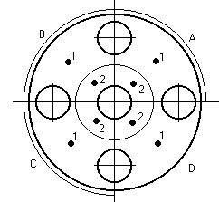
Miniature model Heat Exchanger.
A small heat exchanger was being used alongside a much bigger one to act as a surrogate that could be checked for its behaviour to make estimates of what might be going on inside the big one. Fouling is a key issue in industrial heat exchangers.
The idea was that by running the small exchanger with the same metal walls, same fluid, same wall temperatures and heat flux rate, and importantly the same Reynold's number as the real one, it would foul up in the same way. Then, if calibrated to measure the heat transfer coefficients, it could act as a monitor on process conditions and operational economics for its big brother.
Problems appear
In principle it's easy. In practice a lot of problems arose. The small exchanger needed only low flow rates which were difficult to measure because the dirt and debris in the process water (it was a cooling system), would block up any moving components or orifice plate in the narrow pipes. In the big exchanger it went by with no trouble. We could measure the heat flux into the little exchanger as an electrical power input, but the physical construction meant that the walls had significant dynamic lags for temperature changes. The biggest problem came from the need to make the device give a good estimate of heat transfer reduction due to fouling even though the flow rate could vary over a wide range.
Construction.
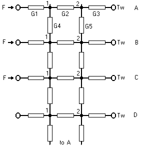
In the diagrams the cross section shows a heater jacket round A, B C quadrants. The water flows through the little hole in the middle. Asymmetry was a potential problem. The ring of bolt holes in the construction made some difference to the heat transfer. The conductance model has all the interesting stuff included in G3. The dynamic model, having thermal capacity at the nodes, allowed us to understand the way the external power controller (not shown) responded to changes when told to provide either constant heat flux or constant temperature (which had to be estimated) at the wall.
Another problem to sort out was the effect of the conduction along the entry and exit pipes that affected the measurements of inlet and outlet water temperatures. Because we were looking for small diffeences, thermocouple matching and calibration also became an issue.
Extracting the answer.
The idea is that the resistance to heat flux comes from the metal (not much), from the fouling layer and from the boundary layer, where the transition from zero velocity at the wall surface to full stream velocity takes place.We were, as usual dealing with turbulent flow. Ideally the model system should measure the temperature drop between wall and fluid and compare it to heat flux to get a reading of heat transfer coefficient. Then the trick is to assign the total resistance between the various contributors. The metal is pretty much a constant thermal resistance, the fouling is the unknown and so we need to know the contribution from the boundary layer, assuming we can measure flow.
Tests and a working system.
When we tested the system for measured heat transfer at variable flow we expected the effects of flow to match the textbook ideas of Reynold's analogy. Well, it did, sort of. But, it wasn't good enough for use in an instrument. I developed mathematical models of the process which allowed for Reynolds number and Prandtl number changes, using essentially the Dittus and Boelter correlation, with the exponent 0.4 on Pr for heating of fluid). This was merged into a form that could be used to create calibration curves for the instrument at two levels. At the simplest level, an assumed power law dependence on flow was taken which gave a good first indication for a model exchanger. If test data over a range of flows and temperatures was available then the mathematical model could be refined for the particular device. I also devised a means of doing away with the flow meter.
Eventually, under pressure as it were, we were able to generate calibration curves from initial running data of a newly installed device even when the controller for the heat input was misbehaving. It took a bit of work with Mathcad but came out well in the end.
Home/Index Page
About Dr McCann
Summary
Dr M.J.McCann
Training Courses
Bristol University
Contacting me
Contact in UK
Location USA
Philosophy
Software Tools
Fees
Confidentiality
 Applications
Business & Commerce
TV Advertising
Drugs Competition
Housing Demand
Automobiles Demand
Wallcoverings Battle
Cash Flow
Human Resources
Project Management
Patent Analysis
Chemical Industry
Cooling Tower
Fermentation
Polymer Process
Heat exchange
Supercritical Fluid
Distributed parameter
Toxic gas allocation
Electrical
Control systems
Initiation systems
Ferrite Filters
Microstrip Antennas
Lightning
Production & Process
Automated manufacture
Crimp and Press
Glass making
Glass molding
Glass to metal seals
Heat exchanger
Helium Leak Testing
RF Soldering
Vacuum web coating
If you have a problem with the behaviour of a market sector, plant, process or item of equipment and would like to get a quantitative handle on it to improve yield or optimise performance, then contact me. I'm always ready to give a little time to discuss a new puzzle, in confidence, of course. We'll only worry about fees when there is some defined work. I can be flexible about how I work with you.
Top
POB 902,
Chadds Ford PA
19317 USA.
T: 1 302 654-2953 (Land)
M: 1 302 377-1508 (Cell)
E: mjmccann@ieee.org
File: toroid.htm